- 您现在的位置:买卖IC网 > Sheet目录333 > ISL2100AAR3Z (Intersil)IC DVR HALF-BRDG HF 100V 2A 9DFN
ISL2100A, ISL2101A
N
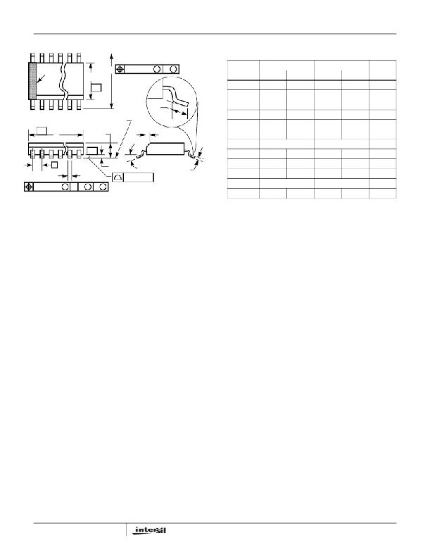
Small Outline Plastic Packages (SOIC)
M8.15 (JEDEC MS-012-AA ISSUE C)
8 LEAD NARROW BODY SMALL OUTLINE PLASTIC PACKAGE
INDEX
AREA
E
-B-
H
0.25(0.010) M
B M
SYMBOL
A
INCHES
MIN MAX
0.0532
0.0688
MILLIMETERS
MIN MAX
1.35
1.75
NOTES
-
A1
0.0040
0.0098
0.10
0.25
-
1
2
3
L
B
0.013
0.020
0.33
0.51
9
C
0.0075
0.0098
0.19
0.25
-
SEATING PLANE
D
0.1890
0.1968
4.80
5.00
3
-A-
D
A
h x 45°
E
0.1497
0.1574
3.80
4.00
4
e
0.050 BSC
1.27 BSC
-
-C-
α
H
0.2284
0.2440
5.80
6.20
-
e
B
A1
0.10(0.004)
C
h
L
0.0099
0.016
0.0196
0.050
0.25
0.40
0.50
1.27
5
6
0.25(0.010) M
C A M
B S
N
α
0°
8
8°
0°
8
8°
7
-
NOTES:
5. Symbols are defined in the “MO Series Symbol List” in Section 2.2 of
Publication Number 95.
6. Dimensioning and tolerancing per ANSI Y14.5M - 1982.
7. Dimension “D” does not include mold flash, protrusions or gate burrs.
Mold flash, protrusion and gate burrs shall not exceed 0.15mm (0.006
inch) per side.
8. Dimension “E” does not include interlead flash or protrusions. Inter-
lead flash and protrusions shall not exceed 0.25mm (0.010 inch) per
side.
9. The chamfer on the body is optional. If it is not present, a visual index
feature must be located within the crosshatched area.
10. “L” is the length of terminal for soldering to a substrate.
11. “N” is the number of terminal positions.
12. Terminal numbers are shown for reference only.
13. The lead width “B”, as measured 0.36mm (0.014 inch) or greater
above the seating plane, shall not exceed a maximum value of
0.61mm (0.024 inch).
14. Controlling dimension: MILLIMETER. Converted inch dimensions
are not necessarily exact.
10
Rev. 1 6/05
FN6294.3
May 6, 2010
发布紧急采购,3分钟左右您将得到回复。
相关PDF资料
ISL2111ABZ
IC MSFT DVR HALF-BRG 100V 8-SOIC
ISL6160EVAL2
EVAL BOARD FOR ISL6160/HIP6006
ISL6207CBZ
IC DRIVER MOSFET DUAL SYNC 8SOIC
ISL6208ACBZ
IC MOSFET DRVR SYNC BUCK 8-SOIC
ISL6208CBZ-T
IC MOSFET DRVR SYNC BUCK 8-SOIC
ISL6209CB-T
IC MOSFET DRVR SYNC BUCK 8-SOIC
ISL6210CRZ
IC MOSFET DRIVER DUAL SYNC 16QFN
ISL6244EVAL1
EVALUATION BOARD ISL6244
相关代理商/技术参数
ISL2100AAR3Z-T
功能描述:功率驱动器IC 100V/2A H-BRDG DRVR 9LD 3X3 CMOS INPUT RoHS:否 制造商:Micrel 产品:MOSFET Gate Drivers 类型:Low Cost High or Low Side MOSFET Driver 上升时间: 下降时间: 电源电压-最大:30 V 电源电压-最小:2.75 V 电源电流: 最大功率耗散: 最大工作温度:+ 85 C 安装风格:SMD/SMT 封装 / 箱体:SOIC-8 封装:Tube
ISL21010
制造商:INTERSIL 制造商全称:Intersil Corporation 功能描述:Micropower Voltage Reference
ISL21010_1112
制造商:INTERSIL 制造商全称:Intersil Corporation 功能描述:Micropower Voltage Reference
ISL21010CFH315Z-TK
功能描述:基准电压& 基准电流 PBFREE PRECISION 1 50V LW V FGA"F 0 2% RoHS:否 制造商:STMicroelectronics 产品:Voltage References 拓扑结构:Shunt References 参考类型:Programmable 输出电压:1.24 V to 18 V 初始准确度:0.25 % 平均温度系数(典型值):100 PPM / C 串联 VREF - 输入电压(最大值): 串联 VREF - 输入电压(最小值): 分流电流(最大值):60 mA 最大工作温度:+ 125 C 封装 / 箱体:SOT-23-3L 封装:Reel
ISL21010CFH320Z-TK
功能描述:基准电压& 基准电流 PBFREE PRECISION 2 048V LW V FGA"F 0 2% RoHS:否 制造商:STMicroelectronics 产品:Voltage References 拓扑结构:Shunt References 参考类型:Programmable 输出电压:1.24 V to 18 V 初始准确度:0.25 % 平均温度系数(典型值):100 PPM / C 串联 VREF - 输入电压(最大值): 串联 VREF - 输入电压(最小值): 分流电流(最大值):60 mA 最大工作温度:+ 125 C 封装 / 箱体:SOT-23-3L 封装:Reel
ISL21010CFH325Z-TK
功能描述:基准电压& 基准电流 PBFREE PRECISION 2 50V LW V FGA"F 0 2% RoHS:否 制造商:STMicroelectronics 产品:Voltage References 拓扑结构:Shunt References 参考类型:Programmable 输出电压:1.24 V to 18 V 初始准确度:0.25 % 平均温度系数(典型值):100 PPM / C 串联 VREF - 输入电压(最大值): 串联 VREF - 输入电压(最小值): 分流电流(最大值):60 mA 最大工作温度:+ 125 C 封装 / 箱体:SOT-23-3L 封装:Reel
ISL21010CFH330Z-TK
功能描述:基准电压& 基准电流 PBFREE PRECISION 3 00V LW V FGA"F 0 2% RoHS:否 制造商:STMicroelectronics 产品:Voltage References 拓扑结构:Shunt References 参考类型:Programmable 输出电压:1.24 V to 18 V 初始准确度:0.25 % 平均温度系数(典型值):100 PPM / C 串联 VREF - 输入电压(最大值): 串联 VREF - 输入电压(最小值): 分流电流(最大值):60 mA 最大工作温度:+ 125 C 封装 / 箱体:SOT-23-3L 封装:Reel
ISL21010CFH333Z-TK
功能描述:基准电压& 基准电流 PBFREE PRECISION 3 30V LW V FGA"F 0 2% RoHS:否 制造商:STMicroelectronics 产品:Voltage References 拓扑结构:Shunt References 参考类型:Programmable 输出电压:1.24 V to 18 V 初始准确度:0.25 % 平均温度系数(典型值):100 PPM / C 串联 VREF - 输入电压(最大值): 串联 VREF - 输入电压(最小值): 分流电流(最大值):60 mA 最大工作温度:+ 125 C 封装 / 箱体:SOT-23-3L 封装:Reel
